Correct air regulator adjustment is the foundation of a stable pneumatic system, directly affecting actuator force, cycle time and compressed air energy consumption. When air regulator adjustment is done correctly, downstream pressure remains constant even as demand fluctuates, protecting valves and cylinders from overload while avoiding wasteful over‑pressure. This practical guide walks you through preparation, step‑by‑step adjustment, verification and troubleshooting so technicians and engineers can confidently set air regulators for repeatable, stable performance.

TABLE OF CONTENTS
- Air Regulator Basics and Why Adjustment Matters
- What an Air Regulator Does in an FRL
- Key Terms: Setpoint, Inlet Pressure and Pressure Drop
- Preparation and Safety Before Air Regulator Adjustment
- Tools and Instruments You Need
- Lockout, Tagout and Depressurization Steps
- Step-by-Step Air Regulator Adjustment Procedure
- Initial Setup and Zeroing
- Raising, Fine-Tuning and Locking the Set Pressure
- Verifying Stable Pressure and Troubleshooting Issues
- Checking Pressure Stability Under Load Changes
- Common Problems After Air Regulator Adjustment
- Advanced Tips for Air Regulator Adjustment in Real Plants
- Setting Different Zones and Point-of-Use Regulators
- Documenting Settings for Quality and Energy Management
- FAQ: Air Regulator Adjustment
Air Regulator Basics and Why Adjustment Matters
What an Air Regulator Does in an FRL
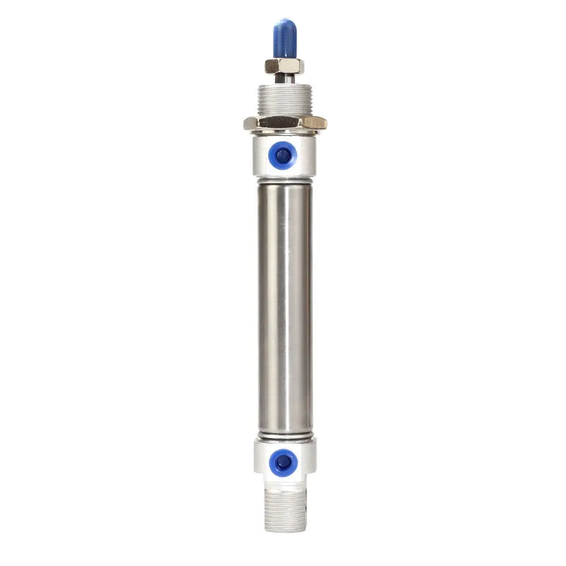
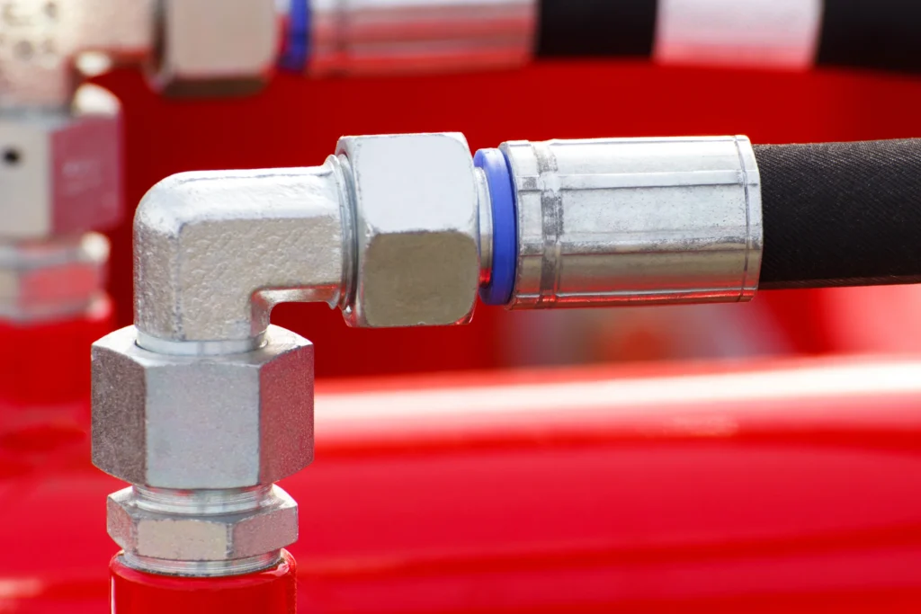
An air pressure regulator is the “control valve” between the compressed air supply and your pneumatic equipment. Its job is to reduce a higher, fluctuating inlet pressure to a lower, stable outlet pressure that matches the requirements of valves, cylinders and tools downstream. Unlike a simple needle valve or ball valve, a regulator uses a spring-loaded diaphragm and internal valve seat to automatically compensate for inlet pressure spikes and downstream demand changes.
In a typical FRL assembly, the regulator sits after the air filter and before the lubricator (if used). The filter removes solid and liquid contamination, while the regulator ensures that only the desired pressure reaches sensitive components. Proper air regulator adjustment keeps actuators from being over‑pressurized (which can damage seals and increase wear) and prevents under‑pressurization that would cause weak, slow motion and inconsistent process results.
Key Terms: Setpoint, Inlet Pressure and Pressure Drop
Before performing any air regulator adjustment, it helps to understand three key terms:
- Setpoint (outlet pressure setting):
The pressure you dial in using the regulator’s adjustment knob. This should match the pressure required by the most sensitive downstream device or by the process specification. - Inlet pressure:
The compressed air pressure supplied to the regulator from the main line or compressor. Good practice is to have inlet pressure at least 1–2 bar higher than the highest required outlet setpoint to give the regulator room to work. - Pressure drop:
The reduction in pressure caused by flow through the regulator and downstream piping. Excessive pressure drop at high flow can make it appear that the regulator is misadjusted, even when its static setpoint is correct.
Knowing these values and how they interact will make your air regulator adjustment more accurate and repeatable, especially in systems where demand changes throughout the production shift.
Preparation and Safety Before Air Regulator Adjustment
Tools and Instruments You Need
Although turning a regulator knob looks simple, professional air regulator adjustment uses proper tools and instrumentation to avoid guesswork:
- A reliable pressure gauge or built‑in gauge on the regulator to read outlet pressure.
- A reference gauge or calibrated test gauge for critical processes where accuracy matters.
- Basic hand tools (screwdriver, hex key or wrench) to remove protective caps or lock the knob.
- For energy or quality projects, a flow meter or data logger can help relate pressure settings to flow and performance.
Before starting, verify that the regulator you are about to adjust is the correct model and range for the application (for example 0–10 bar vs 0–4 bar) and that its gauge scale covers the target setpoint with good resolution.
Lockout, Tagout and Depressurization Steps
In many cases, air regulator adjustment can be done on a live system, but some situations—such as work inside guarded areas or on critical safety circuits—require full lockout/tagout. Follow your plant procedures, which may include:
- Isolate the air supply upstream using a lockable shutoff or dump valve.
- Depressurize downstream equipment by opening a vent valve or operating a bleed point until gauges read zero.
- Apply lockout/tagout devices and tags where required by safety rules.
- Confirm zero energy state by attempting to operate actuators and verifying no motion.
Once the area is safe, you can restore air step-by-step while monitoring pressure as you adjust, or perform adjustment during controlled startup.
Step-by-Step Air Regulator Adjustment Procedure
Initial Setup and Zeroing
Every air regulator adjustment should start from a known baseline:
- Ensure adequate inlet pressure:
Confirm that supply pressure upstream of the regulator is stable and above the intended setpoint (typically by at least 1–2 bar). - Vent downstream circuit if needed:
If you are resetting the regulator from a previously unknown position, it helps to start with minimal downstream pressure to see the effect of adjustment clearly. - Turn the knob fully counterclockwise (or follow manufacturer instructions) to reduce the outlet setpoint to its minimum. Some regulators require pushing or pulling the knob to unlock before turning.
- Slowly re-pressurize the downstream line by opening any isolation valves, watching the gauge to ensure pressure rises in a controlled manner.
At this stage the regulator should be passing only enough air to bring the outlet toward the low end of its range, giving you full control as you begin fine adjustment.
Raising, Fine-Tuning and Locking the Set Pressure
With the system safely at low pressure, follow this procedure for accurate air regulator adjustment:
- Increase the setpoint gradually:
Turn the adjustment knob clockwise in small increments while watching the outlet gauge. Allow a few seconds after each change for the regulator and system to stabilize. - Reach the target pressure under representative load:
Aim to set the regulator while typical downstream consumption is active (for example, while cylinders are cycling at normal speed). Setting pressure under no-flow conditions can produce misleading results once the system is running. - Fine-tune around the target:
If you overshoot, turn the knob slightly counterclockwise. Many industrial regulators are “relieving” type, meaning they can vent excess pressure automatically when you lower the setting; non-relieving types require downstream venting to reduce pressure. - Lock the setting:
Once satisfied, push down or tighten the knob’s locking mechanism if provided, or install a protective cap. This step prevents accidental changes from vibration, bumping or unauthorized adjustments. - Mark the setting if necessary:
For quality-critical or audited processes, record the final setpoint and, if useful, mark the regulator body or panel with a label showing the intended pressure.
Verifying Stable Pressure and Troubleshooting Issues
Checking Pressure Stability Under Load Changes
After completing air regulator adjustment, verify that the outlet pressure remains stable during normal operating cycles:
- Monitor the gauge during full-speed operation:
Watch for significant dips or spikes when multiple actuators operate at once. A slight fluctuation is normal, but large swings suggest undersizing, excessive pressure drop or supply instability. - Check recovery time:
The regulator should bring pressure back to the setpoint quickly after a large demand event. Slow recovery can indicate that the regulator’s flow capacity is too low for peak usage or that upstream filters are restricting flow. - Compare gauges at different points:
When possible, compare readings at the regulator outlet and at critical points further downstream. A large difference indicates additional pressure drop in piping, hoses or fittings.
If pressure remains within acceptable limits during these checks, your air regulator adjustment is likely correct for the current operating conditions.
Common Problems After Air Regulator Adjustment
If issues persist even after careful adjustment, consider these common causes:
- Regulator too small for the flow demand:
An undersized regulator will show good static setpoint but suffer large pressure droop when demand increases. Upgrading to a larger body size—such as moving from a compact LR-series to a higher-flow AR-BR series regulator—may be necessary. - Clogged upstream filters:
Dirty filter elements in FRL units cause pressure loss before the regulator, making it difficult to maintain stable outlet pressure at high flow. Check and replace filter elements regularly. - Incorrect regulator range:
Using a 0–4 bar regulator for a 6 bar setpoint, or vice versa, will limit adjustment accuracy. Always match the regulator’s range to the intended operating window. - Mechanical damage or worn diaphragm:
Old or damaged regulators may leak or drift even after adjustment. In such cases, replacement with a new unit such as a filter-regulator combination is often more economical than attempting repairs.
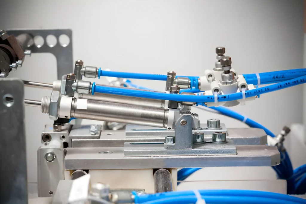
Advanced Tips for Air Regulator Adjustment in Real Plants
Setting Different Zones and Point-of-Use Regulators
In large facilities, a single main regulator at the compressor outlet is rarely sufficient. A more robust strategy layers air regulator adjustment at different levels:
- Main header regulator:
Sets the primary distribution pressure to a value that covers all downstream needs plus reasonable line losses. - Zone or machine regulators:
Provide intermediate control for production lines, ensuring that one area’s demand changes do not excessively affect others. - Point-of-use regulators:
Mounted close to individual tools or cylinders where particularly sensitive pressures are required (for example, low-pressure clamping or delicate product handling).
Using products like AFR/BFR filter-regulator combinations or compact LR-series regulators ensures each critical point has its own local, adjustable pressure control.
Documenting Settings for Quality and Energy Management
Consistent air regulator adjustment is essential for both product quality and energy optimization. Best practices include:
- Standard operating pressures:
Define and document standard setpoints for each line or machine, based on trials and process requirements. Avoid “turn it up until it works” habits that lead to chronic over‑pressure. - Change control:
Require that any adjustment be logged with date, new pressure, reason for change and authorizing person. This makes it easier to trace the cause of later quality or equipment issues. - Energy reviews:
Periodically review regulator setpoints and consider whether some pressures can be safely reduced without affecting performance. Every bar of unnecessary pressure increases compressor energy consumption; careful optimization can deliver significant savings.
By combining technical understanding with disciplined documentation, plants can keep air regulator adjustment under control and aligned with business goals.
FAQ: Air Regulator Adjustment
Q1: Should I adjust the air regulator with the machine running or stopped?
Ideally, regulators should be adjusted while the machine is running under typical load so the setpoint reflects real pressure conditions. However, for safety reasons, some adjustments may start with the machine stopped and then be fine‑tuned during controlled test cycles.
Q2: Why does outlet pressure drop whenever multiple cylinders move at once?
This usually indicates that the regulator or upstream piping cannot supply enough flow for peak demand, causing temporary pressure droop. Possible solutions include using a larger regulator, reducing peak flow demands (for example, staggering actuations) or increasing header size.
Q3: What is the difference between relieving and non-relieving regulators during adjustment?
Relieving regulators can vent excess downstream pressure when you turn the knob down, making it easier to reduce setpoints. Non-relieving types cannot vent, so you