Correctly wiring a DC solenoid valve coil polarity is essential wherever the valve uses built‑in electronics such as LEDs, flyback diodes, rectifiers, or surge protection modules. In many basic coils polarity is not critical, but modern industrial pneumatic solenoid valves frequently integrate polarity‑sensitive components to protect PLC outputs and indicate status, so reverse wiring can stop the valve from working or even damage the protection circuit. This guide explains when polarity matters, how DC solenoid valve coil polarity interacts with protection circuits, and how to wire pneumatic solenoid valves safely and reliably in real automation panels.

TABLE OF CONTENTS
- DC Solenoid Valve Coil Polarity Basics
- When Polarity Does Not Matter
- When Polarity Becomes Critical
- Protection Circuits and DC Solenoid Valve Coil Polarity
- Flyback Diodes and Polarity Requirements
- LED Indicators, Rectifiers and Surge Protection
- How to Wire DC Solenoid Valve Coils Correctly
- Identifying Positive and Negative Terminals
- Step-by-Step Wiring Procedure
- Common DC Coil Polarity Mistakes and How to Avoid Them
- Symptoms of Incorrect Polarity and Miswiring
- Best Practices for Panel Builders and Installers
- FAQ: DC Solenoid Valve Coil Polarity
DC Solenoid Valve Coil Polarity Basics
When Polarity Does Not Matter
From an electromagnetic standpoint, a simple DC coil made only of copper wire around a bobbin will generate a magnetic field regardless of current direction, so basic DC solenoid coils are inherently polarity‑insensitive. In such designs both lead wires are often the same color, and the coil will operate correctly whether the positive supply is connected to either terminal.
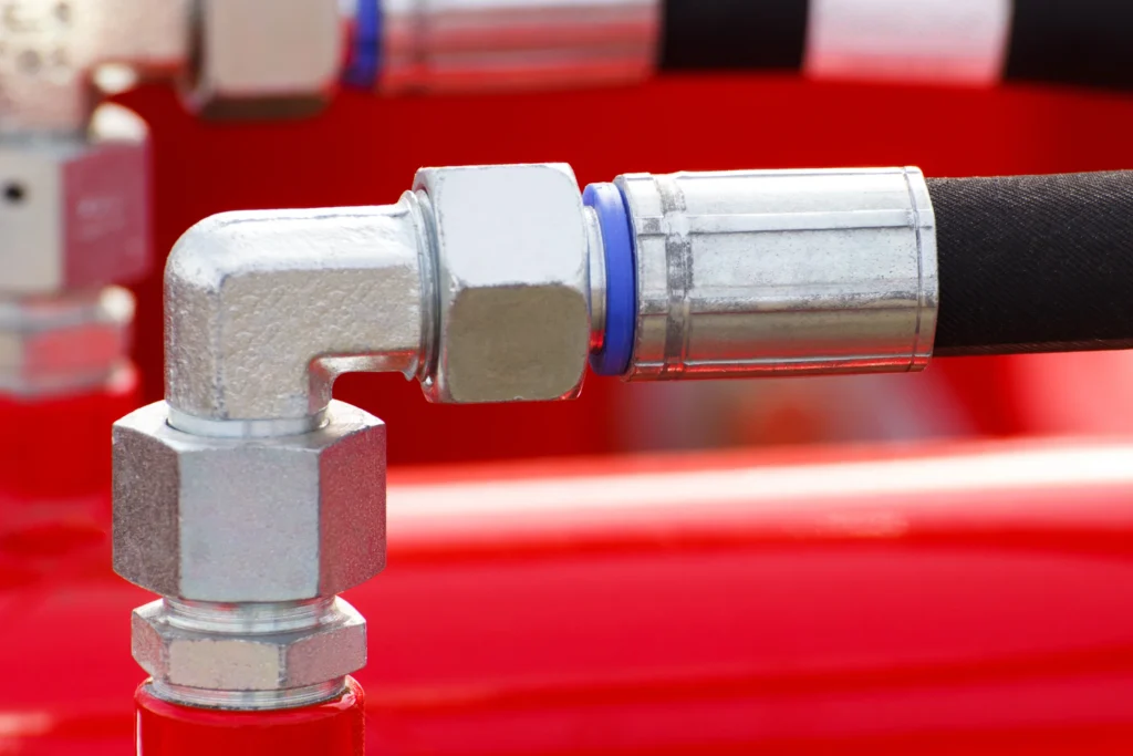
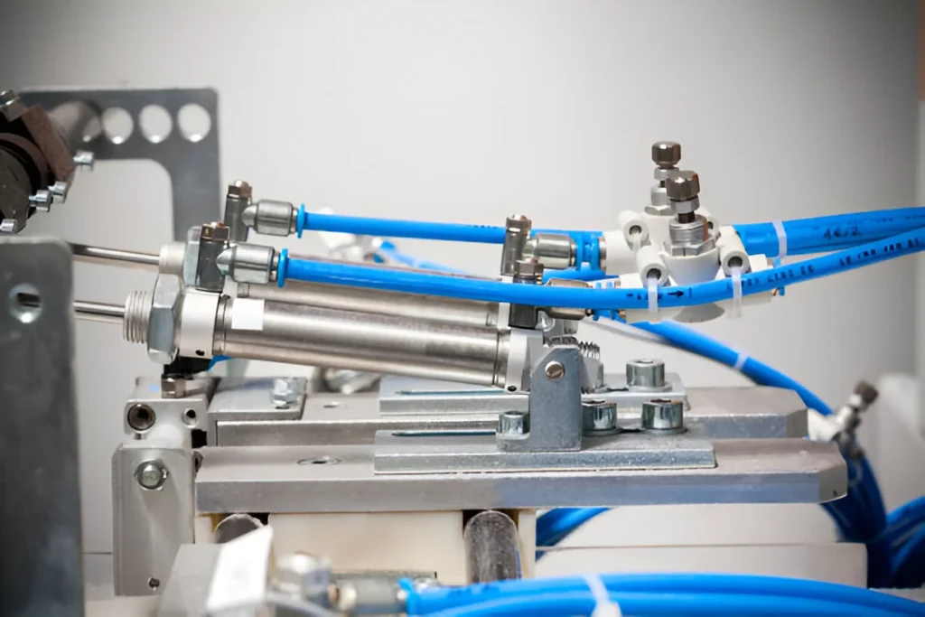
Many traditional pneumatic solenoid valve coils fall into this category, especially those delivered with plain DIN plugs and no internal electronics. For these coils, DC solenoid valve coil polarity is not significant and installers mainly need to ensure the correct nominal voltage, insulation, and strain relief of wires.
When Polarity Becomes Critical
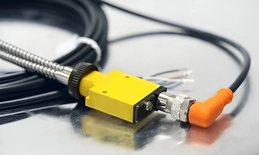
Polarity becomes important when the DC coil assembly includes additional electronic components that depend on current direction. Examples include integrated flyback diodes, polarity protection, LED status indicators, rectifiers that allow AC supply to a DC coil, or combined modules that provide overvoltage protection. In such cases, reverse polarity can prevent current flow, disable the indicator, or overstress the protective component.
Datasheets for polarity‑sensitive coils typically specify which lead or terminal is positive and which is negative, sometimes using different wire colors such as red for positive, black for negative, and green/yellow for protective earth. When working with modern pneumatic solenoid valves, technicians must therefore treat DC solenoid valve coil polarity as a critical parameter rather than an afterthought.
Protection Circuits and DC Solenoid Valve Coil Polarity
Flyback Diodes and Polarity Requirements
A solenoid coil behaves as an inductive load, so when the control signal is switched off, the collapsing magnetic field generates a voltage spike that can damage transistors, relays, or PLC outputs if it is not properly suppressed. A common solution is to place a flyback diode in parallel with the coil, oriented so it does not conduct during normal operation but clamps the voltage spike when the coil is de‑energized.
When a flyback diode is built into the connector or coil assembly, DC solenoid valve coil polarity must be observed carefully. The positive lead must connect to the anode/cathode side defined by the wiring diagram; reversing the supply can forward‑bias the diode continuously, effectively short‑circuiting the power source through the diode and preventing the coil from energizing. This may blow fuses or overheat the diode, resulting in intermittent or complete valve failure.
LED Indicators, Rectifiers and Surge Protection
Many industrial valve plugs incorporate more sophisticated electronics such as LED indicators to show coil status, transient voltage suppressors (TVS diodes), varistors or rectifier bridges, all of which may have polarity‑dependent behavior. For example, a combined LED and diode plug relies on correct current direction for the LED to light and the clamping device to operate correctly.
Some valve connectors include rectifier circuits that allow a DC coil to be driven from an AC supply, or that provide overvoltage protection in both polarities. Even in these designs, the manufacturer usually defines specific pin assignments and sometimes polarity markings for the DC side of the circuit. Therefore, when using advanced coil or connector options with pneumatic solenoid valves, reading the wiring diagram and respecting DC solenoid valve coil polarity is essential for both safe and reliable operation.
How to Wire DC Solenoid Valve Coils Correctly
Identifying Positive and Negative Terminals
The first step in correct wiring is to identify whether a given DC solenoid coil is polarity‑sensitive. Clues include:
- Markings or symbols on the coil body or nameplate indicating “+” and “−” or specific terminal numbers.
- Documentation noting integrated LED, diode or electronic protection circuits that require defined polarity.
- Different colored leads, often red (positive) and black (negative), instead of two identical wires.
If the coil has no such markings and the datasheet explicitly states that polarity is not important, then DC solenoid valve coil polarity can be treated as non‑critical, though consistent wiring practices are still recommended for clarity.
Step-by-Step Wiring Procedure
A safe, repeatable wiring process for pneumatic DC solenoid valves typically follows these steps:
- Confirm coil type and voltage
- Check the coil label for voltage, power rating, and any notes on built‑in electronics or polarity.
- Ensure the power supply and PLC or relay outputs match the coil’s rated voltage and current requirements.
- Plan polarity and grounding
- Assign a standard color and terminal for positive and negative throughout the panel.
- If present, connect protective earth (PE) to the designated ground terminal or green/yellow wire.
- Connect positive and negative leads
- For polarity‑sensitive coils, connect the positive supply to the marked “+” or red lead, and the negative to the “−” or black lead according to the manufacturer diagram.
- Tighten terminal screws securely and ensure no stray strands can cause shorts.
- Check connections with a multimeter
- Verify continuity from the control device to the coil terminals and confirm there are no unintended shorts between positive and negative or to earth.
- Functional test under load
- Energize the valve with system air available, and confirm both electrical behavior (LED status, coil current) and pneumatic switching (cylinder movement, pressure change).
- Observe DC solenoid valve coil polarity behavior: an incorrectly wired protection module may prevent operation, while correct wiring allows normal clicking and flow.
Following this standardized procedure reduces start‑up issues and simplifies future troubleshooting on lines that use multiple pneumatic solenoid valves.
Common DC Coil Polarity Mistakes and How to Avoid Them
Symptoms of Incorrect Polarity and Miswiring
When DC solenoid valve coil polarity is wrong on a polarity‑sensitive coil or connector module, technicians often observe one or more of these symptoms:
- The valve does not actuate at all, even though the control system indicates it is energized.
- Fuses or circuit breakers trip immediately when the output is turned on, especially with built‑in flyback diodes wired in reverse.
- LED indicators fail to light or glow only dimly, suggesting that current is not flowing as designed.
- Coils or connectors become unusually warm, indicating stress on electronic protection components rather than normal coil heating.
In contrast, a truly polarity‑insensitive coil wired backwards relative to some arbitrary convention will still function normally, which is why reading the documentation is so important for accurate DC solenoid valve coil polarity assessment.
Best Practices for Panel Builders and Installers
To minimize polarity‑related problems in pneumatic control cabinets:
- Standardize drawing symbols and labeling so the positive and negative rails, coil terminals and protective devices are always represented in the same way.
- Use pre‑wired connector kits from the valve manufacturer for series like SY reversing valves, which integrate LEDs and protection circuits with clearly marked polarity.
- Document any special coils (for example, those with 12–24 VDC universal ranges, rectifiers or smart drivers) separately in the bill of materials and maintenance manuals, highlighting their polarity requirements.
These practices help ensure consistent wiring, easier training for new technicians, and faster fault location when a DC solenoid valve does not behave as expected.
FAQ: DC Solenoid Valve Coil Polarity
Q1: Does polarity always matter for a DC solenoid valve coil?
No. For simple DC coils without additional electronics, the magnetic field depends on current magnitude, not direction, so the coil is usually polarity‑insensitive. Polarity becomes important when the coil assembly includes components such as diodes, LEDs or rectifiers that rely on a specific current direction.
Q2: How can I quickly tell if a coil is polarity‑sensitive?
Look for polarity markings on the coil or connector, different colored leads such as red and black, or references in the datasheet to built‑in protection or LED indicators. If these are present, assume the coil is polarity‑sensitive and follow the wiring diagram precisely.
Q3: What happens if I reverse the polarity on a coil with an internal flyback diode?
Reversing polarity can forward‑bias the diode continuously, causing a short circuit path that prevents proper coil energization and may blow fuses or damage the diode. The valve will typically not actuate even though voltage is present at the terminals.
Q4: Are AC solenoid coils affected by polarity in the same way as DC coils?
AC coils are driven by alternating current and therefore do not have a fixed polarity in normal operation. However, if a rectifier or electronic driver is used to power a DC coil from an AC supply, the DC side still has polarity considerations similar to pure DC systems.
Q5: Why do some universal 12–24 VDC coils mention polarity in their datasheets?
Universal range coils often include internal electronics to manage current and provide protection, which introduces polarity sensitivity even though the magnetic part of the coil would otherwise be symmetric. In such cases, respecting DC solenoid valve coil polarity is required to ensure both performance and longevity of the electronics.
Related Pneumatic Products from cnzzjyt.com
- 3V Series 3/2 Solenoid Valve 100
- 4V Series Reversing Solenoid Valve 300
- 2S Series 2/2 Solenoid Valve
- VT Series Solenoid Valve
- SY Series Compact Reversing Solenoid Valve
- AF-BF Series Air Filter for Clean, Dry Supply
- AR-BR Series Air Regulator for Stable DC Coil Supply Pressure